I have noticed that published images taken by the James Webb telescope have stars with four diffraction spikes. The secondary mirror for the Webb consists of three struts located 120 degrees apart. Why are there four diffraction spikes in the images and not three?
James Webb images
Well Written Engaging
If there is a JWT whole telescope image showing diffraction spikes in addition to the test image showing 18 images, one taken by each panel, of the same star in Ursa Major could you please post a link.
scott
scott
The photos of individual star images from each panel that I have seen show 6 spikes. The secondary support struts will produce spikes, but so may the edges of each hexagonal panel. Note the support is a tripod, however it is not an exact tripod with legs separated at 120 degrees. Such a setup with a single primary mirror would be expected to have 6 spike pattern. However, the two lower struts, while spaced more closely together do appear to traverse the mirror at the same angle that a perfect 120 degree tripod would do. And it looks like they are also parallel to the edges of the mirror segments. If they are not, one might expect and even more complex pattern of diffractions spikes. The extra complexity may come from the edges if their final collimated positions deviate a bit from the perfect 120 degrees. That may exist anyway because the individual panel edges of the internal panels may present slightly different angles to the incoming light. I am not a whiz at such geometry.
Alan
Alan
Helpful Insightful Respectful Engaging
Having retired from Steward Observatory Mirror Lab as a Tech. I am aware of what SHOULD be there and have seen on NASA images online just what I would expect, however, on Youtube the images released by NASA (supposedly) clearly show the four (or two depending how you define spikes) that are apparent on traditional Newtonian telescopes. Very small spikes are apparent which you could expect in a system with adjustable supports, but the dominant spikes don't seem to represent a system with three primary struts supporting the secondary. I appreciate your inputs and have considered such but was hoping to get a response from an engineer that could respond with an explicit explanation. You may well be right but Keck is segmented and doesn't seem to have odd diffration spikes. Given the precision with which the segments are aligned I would think it unlikely that the mating surfaces would produce visual anomalies, certainly not dominant ones. Thanks for the input, it certainly would explain a lot.
Patrick, I completely agree with your comments. I too would like to hear from a JWST engineer on the question. But it would appear that this is not the forum to find that person. I have seen forums frequented by JWST engineers, surprisingly the JWST Facebook page, so maybe that, or a direct query to the Institute.
I have seen a rather detailed technical answer to you question on Cloudy Nights. Unfortunately not from a JWST person.
I would be stunned that the experts at JWST have not simulated the exact patterns for all the images expected during calibration.
Regarding the mated surfaces between segments, I believe the required spacing between each segment is sufficient to contribute to a pattern. Even the outer edges. The design, however may well bury these contributions under those from the supports.
If you do go elsewhere for the answer you seek, please update this thread!
Alan
Helpful Respectful Supportive
I just saw a video update on an alignment milestone that I think answers the question addressed in this thread. While they do not specifically address the nature of the diffraction patterns or the reasoning, the video clearly shows that in the current state of "diffraction limited" performance, a diffraction pattern is clearly shown to the viewers and can also be seen on any number of computer monitors of the group that was performing the alignment. See here: https://www.youtube.com/watch?v=MiGx8xv6xjE The primary (i.e. the strongest pattern) is a symetrical 6-fold diffraction pattern. In addition, there is a horizontal set of two fainter spikes. The video also shows various images of the individual panel's diffraction spikes under different states of focus. Here, the patterns are variable, as might be expected since their images come from different locations relative to the diffraction-generating features, such as the secondary support and the gaps and edges between panels. For some of these, a 4, or 2 spike image is seen. Though I have to say that as focus of these is reached, they still trend toward a 6 spike image.
I am no expert, but I will go out on a limb and guess that the two faint horizontal spikes are actually part of a 4 spike pattern arising from the vertical and horizontal joint elements between the mirrors and on the peripheral mirror edges. However, we cannot see the vertical spikes because they overlay the vertical components of the 6 spike image.
Either way, the take home message is that the scope, with this detector is exceeding its design and is basically complete in this process! Only thing left is to ensure that the performance is matched with all the other detectors. I hope that this does not reult in any surprises. It would be a brutal process to have to realign/colimate/etc. every time they made a detector swap. I am guessing that they have a means to optimize the detectors to the current condition.
Alan
Helpful Insightful Respectful Engaging
Alan Brunelle:
I just saw a video update on an alignment milestone that I think answers the question addressed in this thread. While they do not specifically address the nature of the diffraction patterns or the reasoning, the video clearly shows that in the current state of "diffraction limited" performance, a diffraction pattern is clearly shown to the viewers and can also be seen on any number of computer monitors of the group that was performing the alignment. See here: https://www.youtube.com/watch?v=MiGx8xv6xjE The primary (i.e. the strongest pattern) is a symetrical 6-fold diffraction pattern. In addition, there is a horizontal set of two fainter spikes. The video also shows various images of the individual panel's diffraction spikes under different states of focus. Here, the patterns are variable, as might be expected since their images come from different locations relative to the diffraction-generating features, such as the secondary support and the gaps and edges between panels. For some of these, a 4, or 2 spike image is seen. Though I have to say that as focus of these is reached, they still trend toward a 6 spike image.
I am no expert, but I will go out on a limb and guess that the two faint horizontal spikes are actually part of a 4 spike pattern arising from the vertical and horizontal joint elements between the mirrors and on the peripheral mirror edges. However, we cannot see the vertical spikes because they overlay the vertical components of the 6 spike image.
Either way, the take home message is that the scope, with this detector is exceeding its design and is basically complete in this process! Only thing left is to ensure that the performance is matched with all the other detectors. I hope that this does not reult in any surprises. It would be a brutal process to have to realign/colimate/etc. every time they made a detector swap. I am guessing that they have a means to optimize the detectors to the current condition.
Alan
Thanks for the detailed reply. My initial question was one of curiosity only. I think the images on the Youtube site were probably Hubble images being passed off as JWST. Particularly because there is nothing in the design of the JWST that would produce four spikes.
Well Written Insightful Respectful Concise
Patrick Stevenson:
I think the images on the Youtube site were probably Hubble images being passed off as JWST.
Patrick,
I completely understand! I have been seeing YouTube titles lately stating wonderful discoveries from JWST. Yeh, right! I specifically try not to look at those, since people make money on this trash. In your case, I bet what you saw was an honest jounalistic action taken to show some sort of image of a "star". Not many journalist are sophisticated enough to know themselves what mistakes they make when trying to convey technical stuff well above their own levels.
I do appreciate what the institutes do now to report their results to the public. Under current political and social pressures scientists need a lift, and they can do themselves proper justice if they stop insulating themselves (as was typical just a decade ago) and participate in the communication to all parts of society, not just their peers.
Take care and CS!
Alan
Thanks for sharing that YouTube video! I see a couple of folks that I know from my work on JWST many years ago (Matt Mountain and Ritva Keski-Kuha–the deputed observatory director). It's fantastic that they have the telescope aligned and phased. The PSF shown in the video looks exactly as expected. There are 6 spikes from the mirror edges and two of the secondary support beams that are aligned with the mirror edges along with a "horizontal" spike from the third secondary support beam that isn't aligned with any of the segment edges.
John
John
Well Written Helpful Insightful Respectful Engaging Supportive
Thanks John! I just realized that there are no edges parallel to the one vertical strut as shown in most face on views. So I can now rest my speculation on those faint horizontal spikes. Either way, the psf and diffraction rings on this image are wonderful considering its an IR image.
I know they have to check things out with the other detectors, but as a tax paying citizen, can we all vote that the team there takes a break and let the imaging team there just take one image of something interesting?!
I know they have to check things out with the other detectors, but as a tax paying citizen, can we all vote that the team there takes a break and let the imaging team there just take one image of something interesting?!
Engaging Supportive
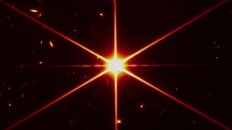
If this is the image you are referring to, I can only hope things get better. The processing leaves a lot to be desired!
https://ichef.bbci.co.uk/news/976/cpsprodpb/5869/production/_123733622_1f935b99-c9fd-4c8c-b4c5-0de8558523de.jpg
https://ichef.bbci.co.uk/news/976/cpsprodpb/5869/production/_123733622_1f935b99-c9fd-4c8c-b4c5-0de8558523de.jpg
Well Written
Stuart Taylor:
If this is the image you are referring to, I can only hope things get better. The processing leaves a lot to be desired!
https://ichef.bbci.co.uk/news/976/cpsprodpb/5869/production/_123733622_1f935b99-c9fd-4c8c-b4c5-0de8558523de.jpg
Rest assured that the first official image will be an apod ...
Clear skies
Wolfgang
Stuart Taylor:
If this is the image you are referring to, I can only hope things get better. The processing leaves a lot to be desired!
https://ichef.bbci.co.uk/news/976/cpsprodpb/5869/production/_123733622_1f935b99-c9fd-4c8c-b4c5-0de8558523de.jpg
This is a cool image and bodes well for Webb. Checking a good number of the survey images available, I could not find any of the Webb imaged galaxies, except maybe a smudge here and there. This image looks considerably deeper than they showed for the calibration shots I was referring too. But I think the dimmer star near the bottom of the frame reveals the quality of the optics at this point and resembles the less exposed images of the control star. I believe that, as a single frame exposure, this is demonstrating resolution at least as good as Hubble. I wish Hubble had imaged this field to compare.
While I have no doubt that they will employ some very good "processing artists" to generate images for public consumption, my guess is that effort has not ramped up yet. Otherwise, I believe the real science will mostly concentrate on things other than heavily massaged imaging.
It will be interesting to see what those artists choose as a color palette for public presentations. And given the rather broad spectrum that they will get from the several imaging instruments I suspect that there may be more than one Webb Palette.
Helpful Insightful Respectful Engaging
Rest assured that the first official image will be an apod ...
Clear skies
Wolfgang
Good call.
One Image, one APOD.
John Hayes:Rest assured that the first official image will be an apod ...
Clear skies
Wolfgang
Good call.
One Image, one APOD.
Call me the Nostradamus of astrobin :-)
Actually I didn't expect that this one will become an apod because I didn't really count it as the first image. It's sort of a calibration shot after all, although certainly one of high significance. Anyway I believe there were tougher predictions to make ...
I'm really enthusiastic about the fact how smooth this really complex project moves forward. Can't wait for the "real" first image and looking forward towards the "James Webb Palette" to present IR images.